- Log in to post comments
Backstory 1 and Backstory 2 and Backstory 3
Finally, I have the new racer in the shop, and the rust has all been cleaned up thanks to Doug Abelin and $350 in sand blasting expenses.
Last weekend, my daughters helped me rag and duct-tape the sensitive parts before we flat-towed the racer the 1/4 mile to Doug's place.
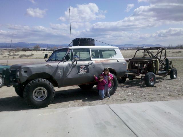
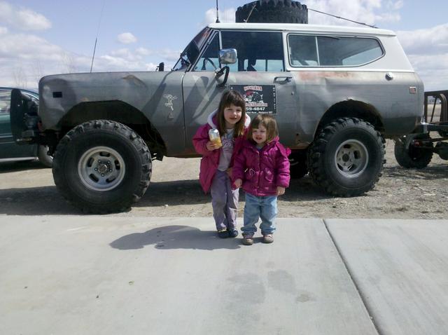
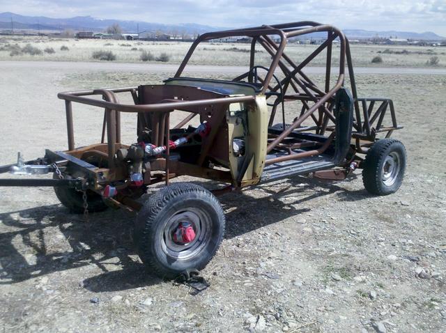
Today, Doug called and said it was ready.
So I headed over to haul it home.
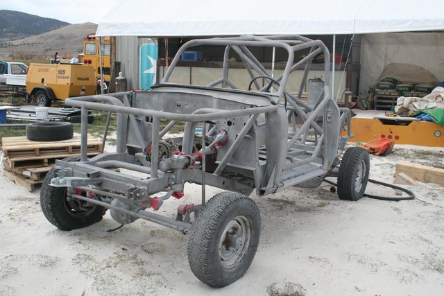
Doug pointed out to me some "craters" in the chassis. Places where a tab or bracket was removed, but the grinder - or the popped weld - took enough of the parent material to leave a depression where the thickness is thinner than it should be, and in some cases, might actually leak oil from the diff.
These will need to be welded up and ground down.
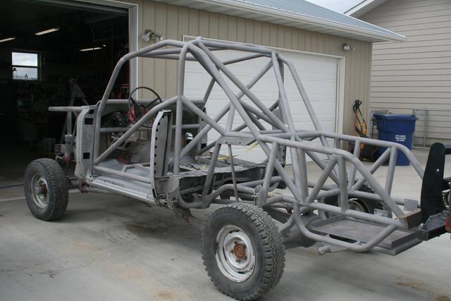
This is on the start of the "back-half" tube-frame.
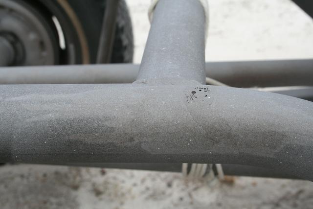
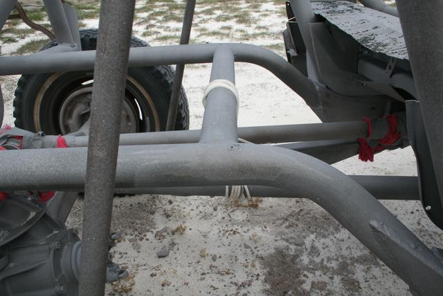
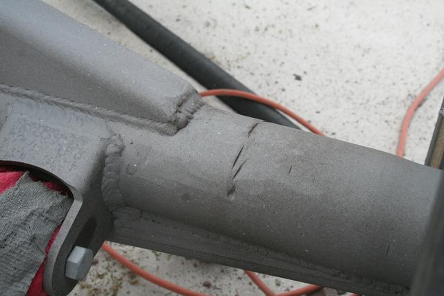
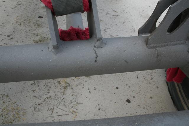
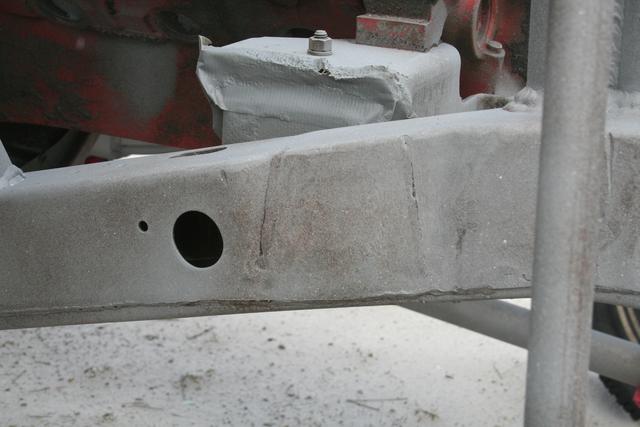
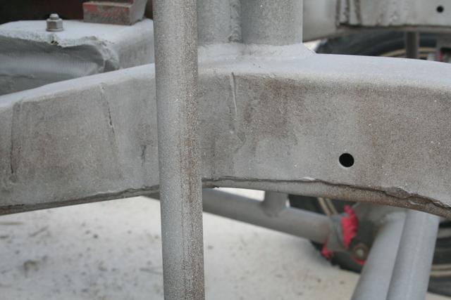
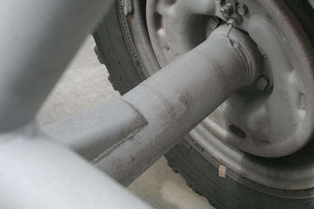
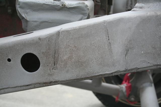
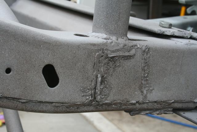
(above, on the frame)
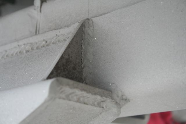
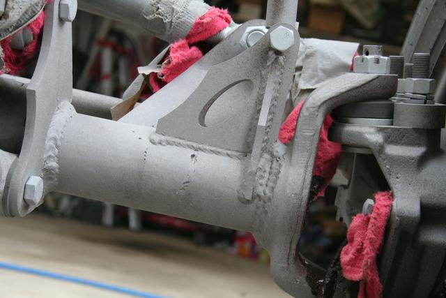
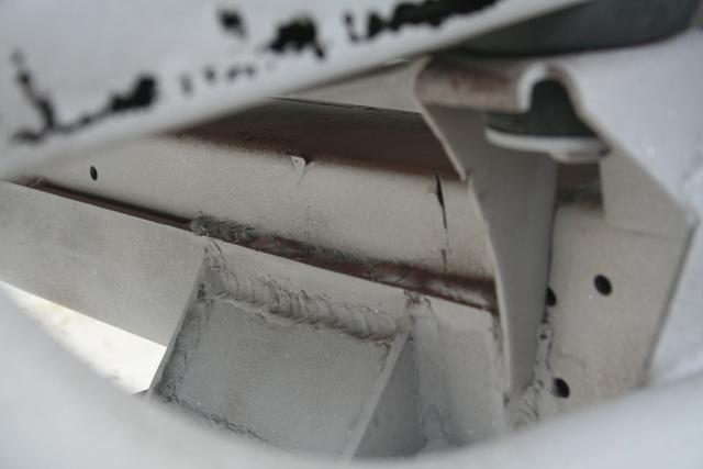
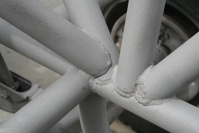
Doug also pointed out unfinished or incomplete welds.
This is where the main structure of the back half attaches to the factory Scout frame below the B-hoop.
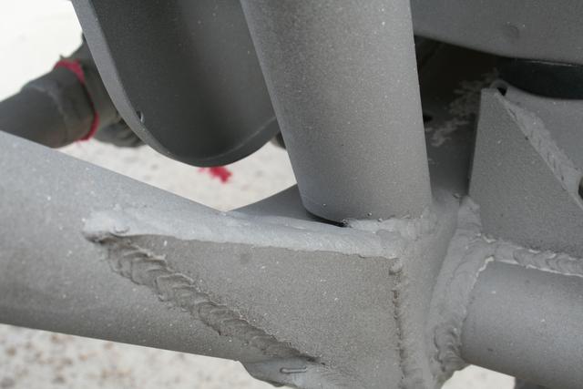
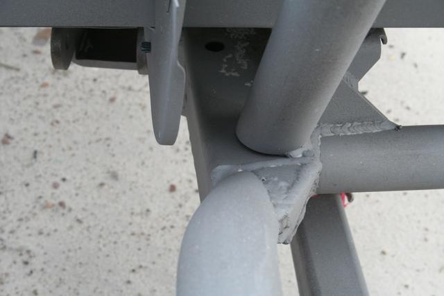
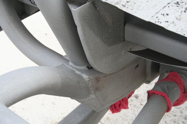
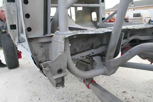
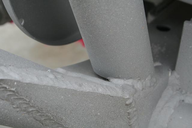
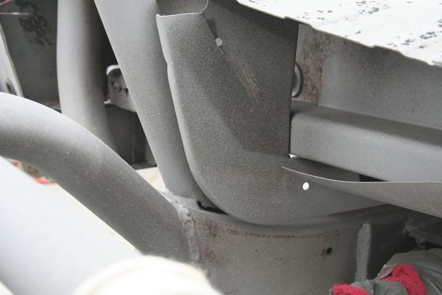
It's a little dark, but that's the front body mount, under the driver's feet, and the stand-off isn't fully welded.
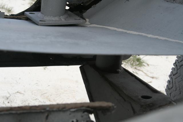
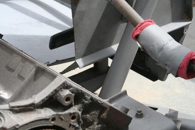
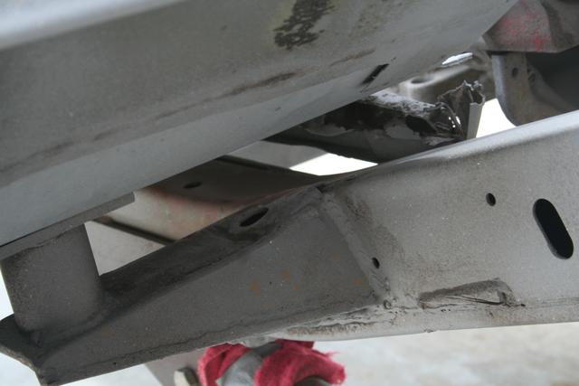
After I removed the barely attached floors, you can see it clearer.
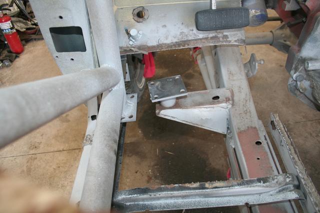
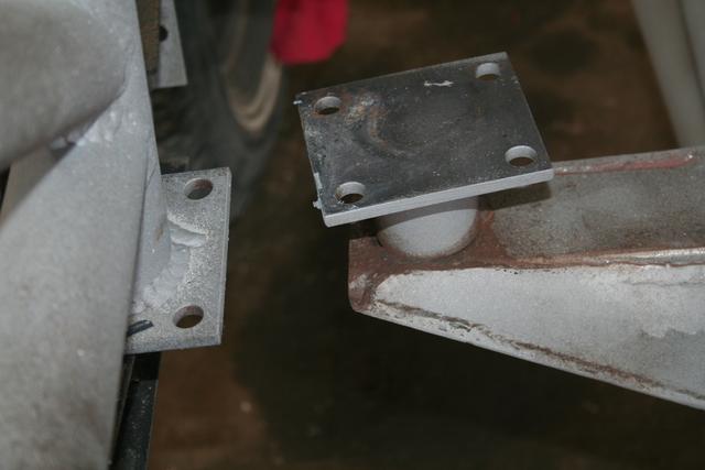
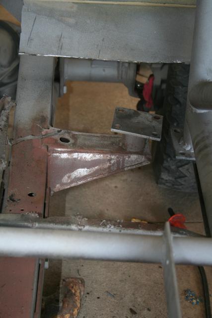
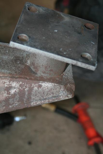
The driver's side was brought to my attention because the driver's floor was damaged during sand blasting (it was rolled onto it's side), but after removing the floor, the passenger side has the same flaw.
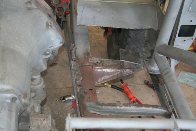
The gussetted body mount could use a little more weld, too.
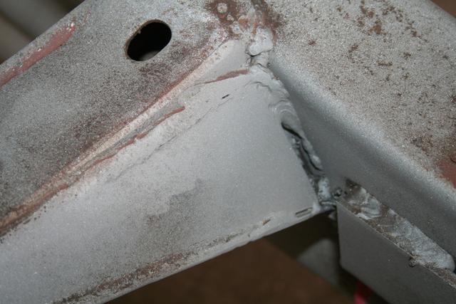
The factory IH frame welds need some attention, too.
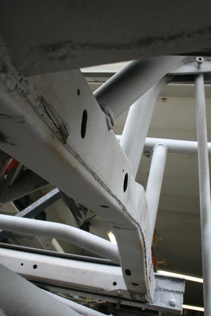
Several examples of good welds to be found, too, of course.
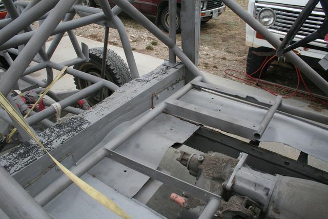
As I mentioned, the driver and passenger floors and rockers were replaced, though not in a fantastic fashion, and the driver's floor was damaged during the blasting, so I had to do something about it.
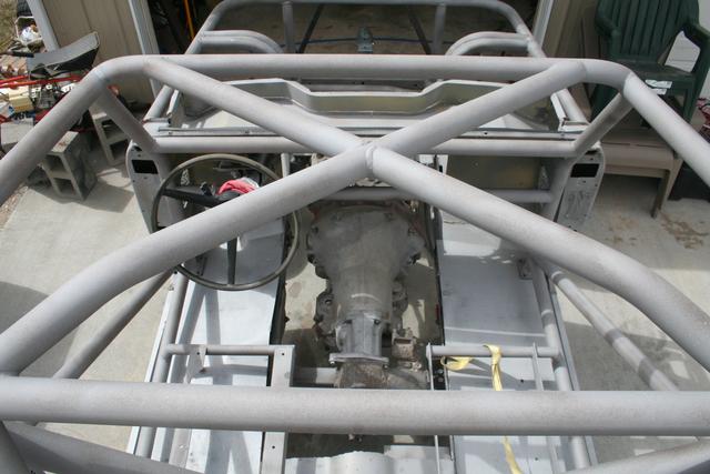
The inner C-channel that runs just between the frame rails was pretty rotten, so this needed to be addressed anyways - along with the need to build a new dog house.
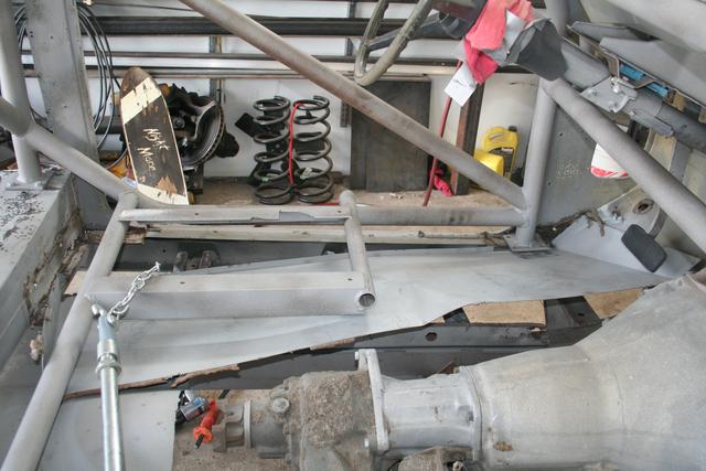
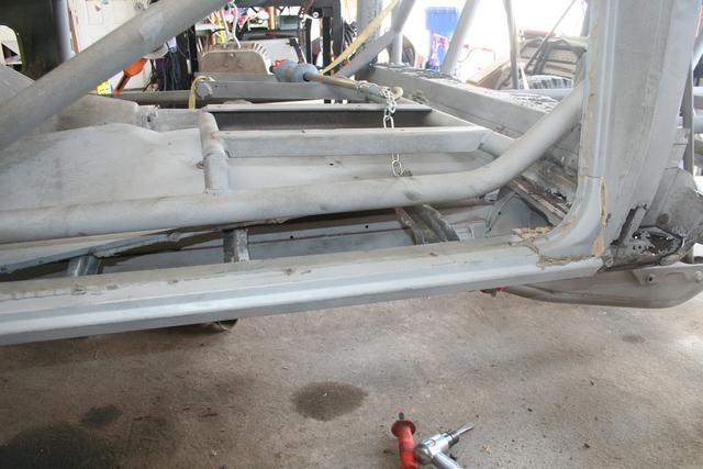
There were a few welds, but mostly silicone caulking or RTV holding everything in place.
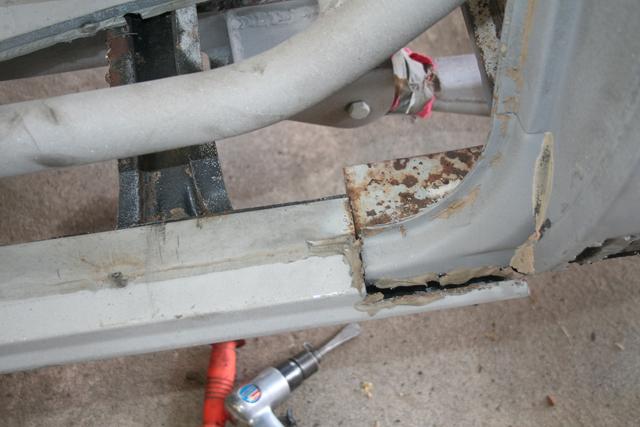
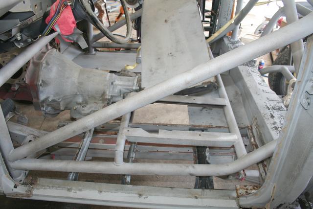
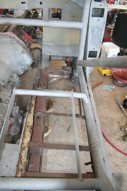
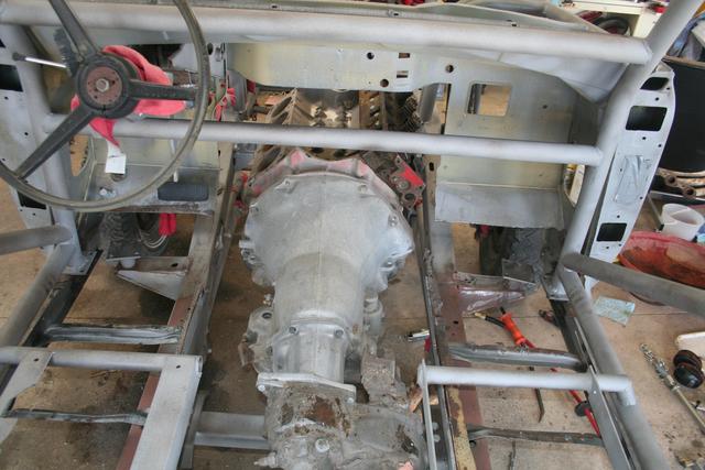
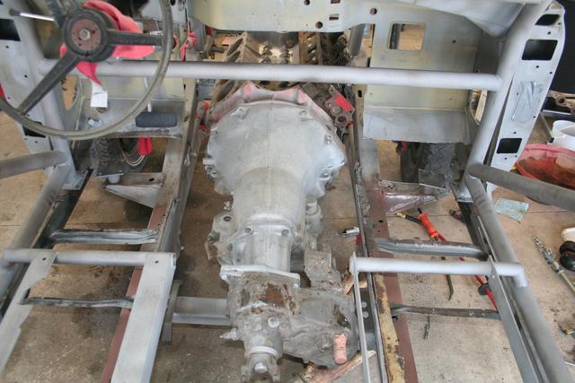
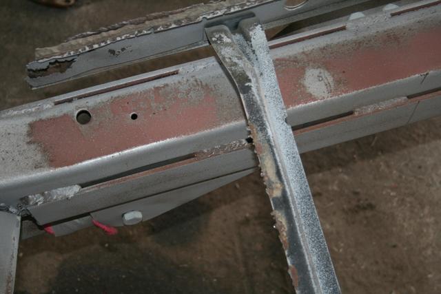
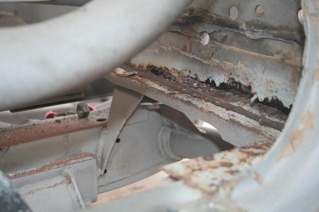
(I knew the chassis had some rust, and already stated I wasn't that worried about it, but since I'm in there and have to do something about the missed welds and such anyhow, I might as well address the floor and any rust that I encounter if it's easy enough to correct)
I think I will remove the factory stringers/floor supports. They are good and strong and light, but the "L" and reverse "L" (really, Z and reverse Z) design likes to catch dirt and mud and keep it there.
I think I will go with something like a light gauge (make it on my brake?) C channel down about the middle of the floor. I will then make the floor in two pieces, front and back, joining at the C. I may put a second C in the front half of the floor, but the rear half is entirely under the seat, which is mounted to the cage, so it's just decorative.
Since I also have to build the doghouse, I think I will bring the "inner C" inboard a bit, and since the thing is already welded to the frame in so many places, I will just stand a piece of angle steel off the frame itself to support the inside end of the floor pan when bolted in. That would also become the starting point for the doghouse/transmission tunnel.
I want to build a center console / transmission hump combination that is also structural. The cage will swoop down from the dash bar and then level out for a bit before dropping to the floor at the "step". The new tunnel will then be built from that to cover the engine, transmission, and scatter shield.
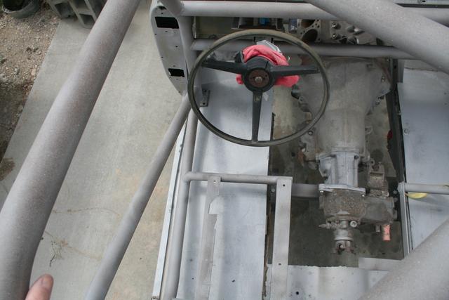
Instruments go in the sharp "swoop down" vertical face, the 12voltguy panel goes on the flatter, more horizontal area, with the ratchet shifter in easy arm's reach on the flat part.
I also want to consider some means of a weather-protection cover for the gauges and switches for those long Montana winters.
There's a lot of tube in this thing.
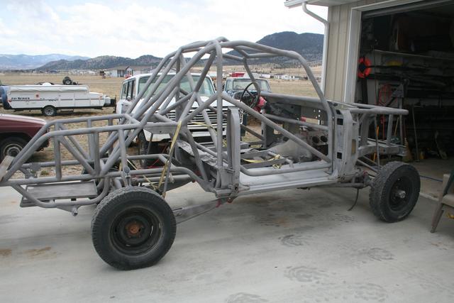
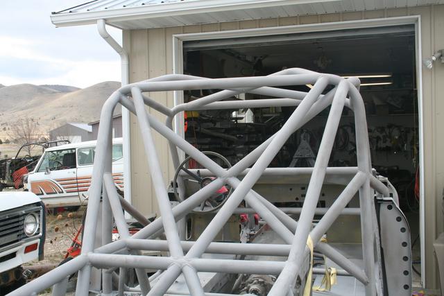
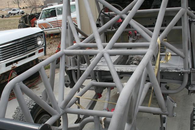
(note that one of the links is disconnected)
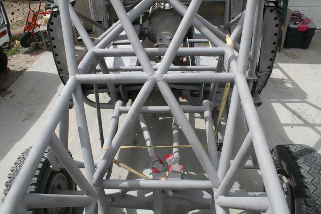
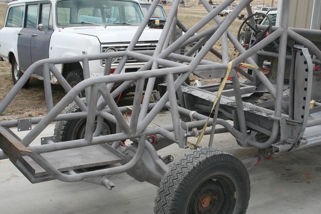
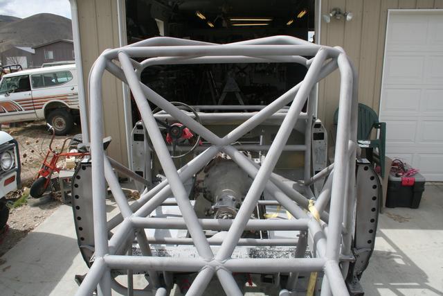

This one gives you an idea of what the cockpit will be like. I have to move the brake pedal over so it can be operated with the left foot, to make room for a gas pedal for the right foot.
Here is something to like about the fabricator's design. This is a piece of plate, bent on a brake, to wrap around the frame. The 4-link tabs are then welded to the sleeve outside of the chassis, before the sleeve is fitted and welded to the frame.
The downside is, it's still hard to weld to the frame, and in this application, since it wasn't fully welded, I would expect debris (mud and such) to accumulate in that gap and rust out the frame and sleeve at some point. Since I had to remove the floors, I will completely weld the sleeve to the frame to seal it up.
Here's another design concern I need to address.
The front engine cage has a few items to address, starting with how it is tied to the main cage.
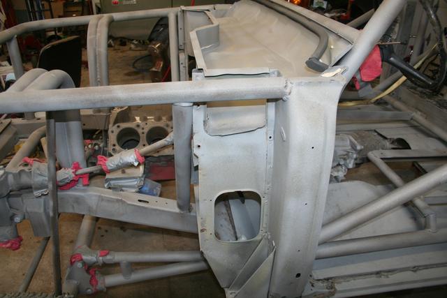
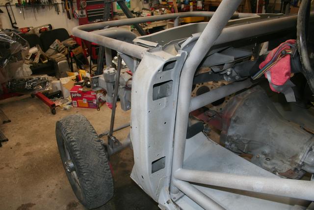
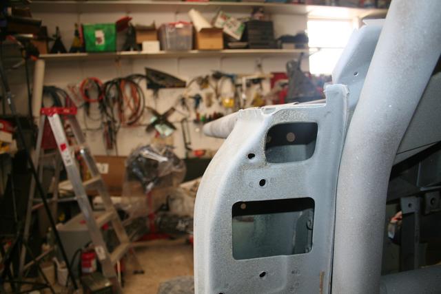
Which is to say, it is not attached.
The engine hoop ties to the frame right in front of the A pillar, and is welded to the A-pillar - a strong part on a stock Scout - but then the main cage is (not yet) bolted to the floor, staggered from the frame stand-off, and is not attached to the A pillar.
I can start with a gusset between the A pillar and A-hoop of the cage, but I might try for something more. Perhaps I can come in from the top side of the A pillar and make an "L" shape piece that ties into the A hoop and goes through the existing hole and more or less can engage the engine hoop.
Another issue is the very front of the engine halo. I intend to X the front opening, and then make the top bar removable so I don't have to raise the engine over my head when R&Ring it.
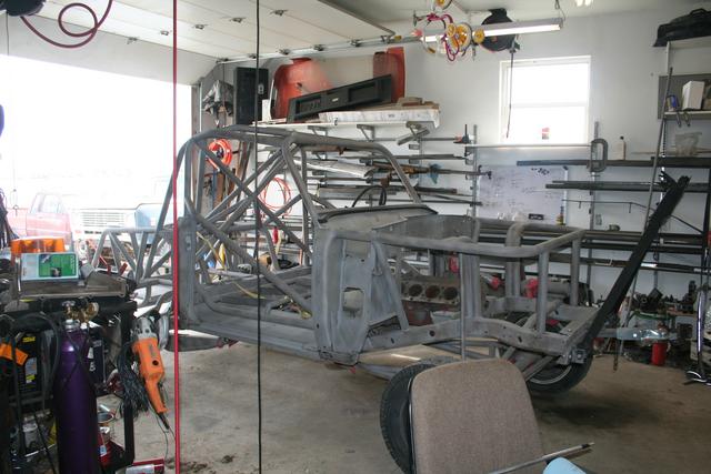
I will then add a removable cross-brace between the two coilover towers, and a radiator mount. It looks like the front air bumps will have to go inboard of the frame to get enough room, with the steering box and then the panhard bar and such all getting in the way at one end or the other.
Now that the Scout is in the shop -
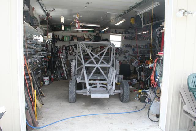
I need to get it done and painted before I shove it back out.
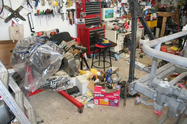
Here, the new engine is awaiting assembly..
And here, off the end of the shop, sits the old racer, Little Devil, after the 2.5 rolls at 50mph last October.
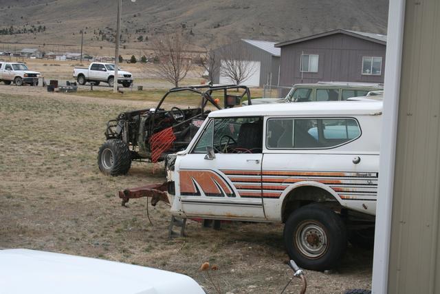
In the foreground is a spare tub and frame (sitting sprung over on a spare Ford Dana 60 FF so I could move it around), originally for a trail rig, though I have a nicer tub and bare frame for that now.
Finally, I have the new racer in the shop, and the rust has all been cleaned up thanks to Doug Abelin and $350 in sand blasting expenses.
Last weekend, my daughters helped me rag and duct-tape the sensitive parts before we flat-towed the racer the 1/4 mile to Doug's place.


Today, Doug called and said it was ready.
So I headed over to haul it home.
Doug pointed out to me some "craters" in the chassis. Places where a tab or bracket was removed, but the grinder - or the popped weld - took enough of the parent material to leave a depression where the thickness is thinner than it should be, and in some cases, might actually leak oil from the diff.
These will need to be welded up and ground down.
This is on the start of the "back-half" tube-frame.
(above, on the frame)
Doug also pointed out unfinished or incomplete welds.
This is where the main structure of the back half attaches to the factory Scout frame below the B-hoop.
It's a little dark, but that's the front body mount, under the driver's feet, and the stand-off isn't fully welded.
After I removed the barely attached floors, you can see it clearer.
The driver's side was brought to my attention because the driver's floor was damaged during sand blasting (it was rolled onto it's side), but after removing the floor, the passenger side has the same flaw.
The gussetted body mount could use a little more weld, too.
The factory IH frame welds need some attention, too.
Several examples of good welds to be found, too, of course.
As I mentioned, the driver and passenger floors and rockers were replaced, though not in a fantastic fashion, and the driver's floor was damaged during the blasting, so I had to do something about it.
The inner C-channel that runs just between the frame rails was pretty rotten, so this needed to be addressed anyways - along with the need to build a new dog house.
There were a few welds, but mostly silicone caulking or RTV holding everything in place.
(I knew the chassis had some rust, and already stated I wasn't that worried about it, but since I'm in there and have to do something about the missed welds and such anyhow, I might as well address the floor and any rust that I encounter if it's easy enough to correct)
I think I will remove the factory stringers/floor supports. They are good and strong and light, but the "L" and reverse "L" (really, Z and reverse Z) design likes to catch dirt and mud and keep it there.
I think I will go with something like a light gauge (make it on my brake?) C channel down about the middle of the floor. I will then make the floor in two pieces, front and back, joining at the C. I may put a second C in the front half of the floor, but the rear half is entirely under the seat, which is mounted to the cage, so it's just decorative.
Since I also have to build the doghouse, I think I will bring the "inner C" inboard a bit, and since the thing is already welded to the frame in so many places, I will just stand a piece of angle steel off the frame itself to support the inside end of the floor pan when bolted in. That would also become the starting point for the doghouse/transmission tunnel.
I want to build a center console / transmission hump combination that is also structural. The cage will swoop down from the dash bar and then level out for a bit before dropping to the floor at the "step". The new tunnel will then be built from that to cover the engine, transmission, and scatter shield.
Instruments go in the sharp "swoop down" vertical face, the 12voltguy panel goes on the flatter, more horizontal area, with the ratchet shifter in easy arm's reach on the flat part.
I also want to consider some means of a weather-protection cover for the gauges and switches for those long Montana winters.
There's a lot of tube in this thing.
(note that one of the links is disconnected)
This one gives you an idea of what the cockpit will be like. I have to move the brake pedal over so it can be operated with the left foot, to make room for a gas pedal for the right foot.
Here is something to like about the fabricator's design. This is a piece of plate, bent on a brake, to wrap around the frame. The 4-link tabs are then welded to the sleeve outside of the chassis, before the sleeve is fitted and welded to the frame.
The downside is, it's still hard to weld to the frame, and in this application, since it wasn't fully welded, I would expect debris (mud and such) to accumulate in that gap and rust out the frame and sleeve at some point. Since I had to remove the floors, I will completely weld the sleeve to the frame to seal it up.
Here's another design concern I need to address.
The front engine cage has a few items to address, starting with how it is tied to the main cage.
Which is to say, it is not attached.
The engine hoop ties to the frame right in front of the A pillar, and is welded to the A-pillar - a strong part on a stock Scout - but then the main cage is (not yet) bolted to the floor, staggered from the frame stand-off, and is not attached to the A pillar.
I can start with a gusset between the A pillar and A-hoop of the cage, but I might try for something more. Perhaps I can come in from the top side of the A pillar and make an "L" shape piece that ties into the A hoop and goes through the existing hole and more or less can engage the engine hoop.
Another issue is the very front of the engine halo. I intend to X the front opening, and then make the top bar removable so I don't have to raise the engine over my head when R&Ring it.
I will then add a removable cross-brace between the two coilover towers, and a radiator mount. It looks like the front air bumps will have to go inboard of the frame to get enough room, with the steering box and then the panhard bar and such all getting in the way at one end or the other.
Now that the Scout is in the shop -
I need to get it done and painted before I shove it back out.
Here, the new engine is awaiting assembly..
And here, off the end of the shop, sits the old racer, Little Devil, after the 2.5 rolls at 50mph last October.
In the foreground is a spare tub and frame (sitting sprung over on a spare Ford Dana 60 FF so I could move it around), originally for a trail rig, though I have a nicer tub and bare frame for that now.